GM Passlock I & II Information
Please study the following information carefully WHEN INSTALLING REMOTE START systems on a 1996 or later GM car or truck.
Introduced in 1996, GM has changed the VATS anti theft system to Pass-Lock system. This is a similar device to the VATS system, in that there is a resistor present during the start cycle. However, in the PASSLOCK system, the resistor has been placed inside the ignition switch, instead of the key. See the GM V.A.T.S page for more information.
To remotely start a car with this feature, you must bypass the PASSLOCK system. There are two methods of doing so.. The first, is to permanently bypass this system. This is the easiest method for accomplishing your task. The second way, is to temporarily bypass the PASSLOCK, by introducing relays into the system, which retain all of the features of the system, while allowing your remotes start module to bypass it automatically during a remote start cycle.
Vehicles effected
(1996 and newer): N & J body cars, such as
Pontiac Sunfire and GrandAm Passlock-1
Chevrolet Cavalier Passlock-1
Buick Skylark Passlock-1
Oldsmobile Achieva Passlock-1
1997 or newer
Chevrolet Malibu Passlock-II
Oldsmobile Cutlass Passlock-II
1998 or newer
All trucks , SUVs and Vans Passlock-II
It is important to pay special attention to the fact that there are many
different ways of achieving the same goal. There are actually 2 different
Passlock-II systems. On the next page, there are tests to establish which
type of passlock-II your car has.
Relays shown are standard automotive 5 pin spdt relays, available from IEI.
A multi meter is required to measure the resistance values. Accuracy is
important within 5%.
Once the value of the resistor is measured, a resistor of the same value
+/-5% must be purchased (Radio Shack, for example). You can also use a
Potentiometer (POT), which can be adjusted to the same value of the
resistor in the ignition switch.

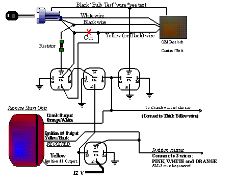
Passlock-I bypass procedure....
1: Remove the top and bottom shrouds from the steering column.
2: Find the 3 wire ribbon cable, coming from the ignition switch, containing White, Black, Yellow (Sometimes White, Black, Black). These are THIN wires.
3: Locate the Black 6 position connector on the LEFT side of the steering column, right above the ignition switch position. There is a BLACK (Thin) wire in this connector, called "Bulb Test", which shows Ground with ignition in the Off position, OPEN in the "Run" position, and GROUND in the "Crank" position.
4: Turn the ignition switch to the "Run" position. Do not crank the car.
5: Cut the Thin Yellow wire and strip both ends.
6: Without cutting the Black wire, expose some of the copper.
7: Using the ohmmeter, measure from the Yellow wire (the end coming from the ignition switch), to the exposed Black wire and record the value. Measure more than once to assure you have the right value.
8: Acquire the same size resistor and 3 relays, and perform the
connections shown in the diagram below.

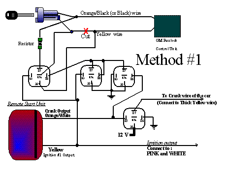
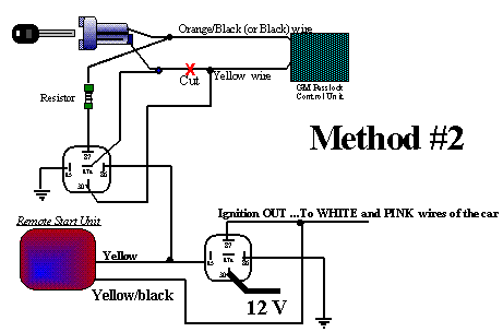
PASSLOCK-II bypass procedure
There are 2 types of Passlock-II systems. To determine which system you
have, follow these instructions;
1: Locate two wires, which are THIN and are in the main ignition harness..
Orange/Black (or Black) and Yellow.
2: Cut the Yellow wire, and strip back some of the insulation from the Orange/Black (Or Black) wires.
3: Turn the ignition to the "Run" position ( don't crank the starter). Measure and record the value measured from the KEY SIDE of the Yellow wire, to the Black/Orange wire.
4: Turn the key to the "Crank" position and release. Now read the value again.
 5: If
the value changed, follow "Method#1". If the value stayed the
same, follow "Method#2".
These diagrams are from our friends at ALARMTEK AUTO ALARM